")
")
DfAM - Design criteria for FFF 3D printing
Filament 3D printing technology (FFF) provides some design criteria, to be followed in order not to run into problems during the printing phase. Let's discuss some of the DfAM (Design for Additive Manufacturing) rules in detail.
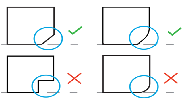
BEVELS AND FITTINGS
The first criterion concerns the edges of the component, as it is advisable to chamfer an edge at 45° or fillet it. The figure shows this small but fundamental trick to avoid the warping phenomenon, i.e. an anomalous deformation with relative lifting from the printing surface which, if it occurs from the beginning, would compromise the part for all the remaining printing time.
BED ADHESION
Print bed adhesion is one of the headaches of those who use technologies in the AM field, and is influenced by multiple parameters such as:
- Print Bed Temperature
- Percentage of overextrusion of the Line Width (20% is recommended)
- Height of the starting layer
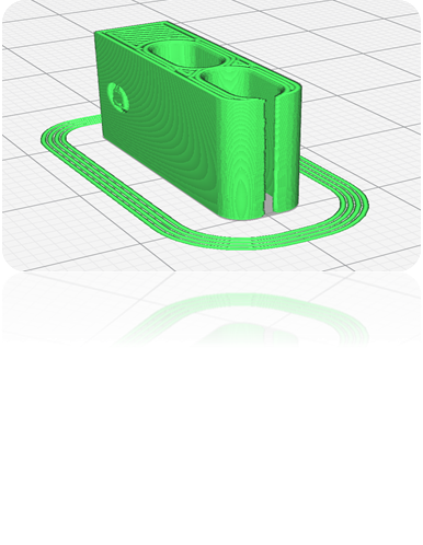
- Using Brim or Raft
- Print speed of the first layer (must be <35mm/s)
- Cooling fan (if a material that does not need to be cooled, volumetric shrinkage or detachment from the plane is obtained)
- Bottom thickness
- Fill percentage (should not be too high)
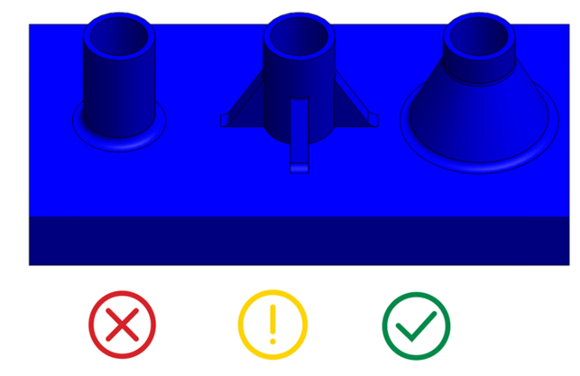
Furthermore, it is very important to design the component in order to best distribute the load on the print bed. An example is shown in the figure.
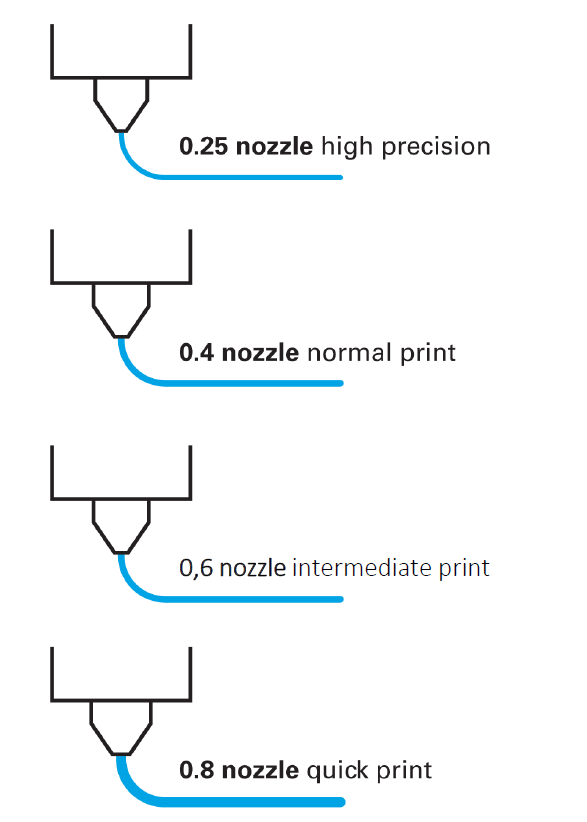
ACCURACY
Good printing accuracy depends more on the diameter of the nozzle you are using. If the thickness of the line is smaller than the nozzle diameter there will be voids on the component (as shown). The maximum pass limit must be no less than 70% of the nozzle diameter.
- a smaller nozzle diameter results in high detail printing
- a larger diameter helps reduce printing time
- a nozzle with a diameter of 0.4 mm is a real compromise, and in fact it is the most used
COMPONENT RESISTANCE
FFF technology is anisotropic, i.e. the characteristics of the component are different and independent of each other along the three directions, and all anisotropic materials do not require cooling. Many times a component is designed with the awareness of having to make it with filament 3D printing, and for this reason it is necessary to take into account how the component must be positioned on the printing surface. Therefore, it is necessary to analyze the forces acting in advance to evaluate the correct orientation of the part, or at least evaluate the functional requirements that the component must possess (aesthetic functions, resistance, etc.).
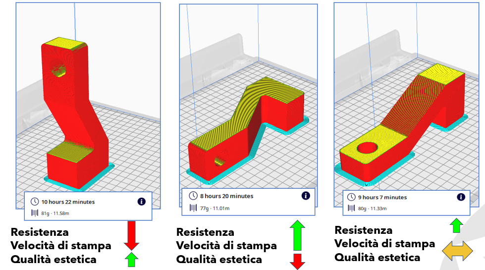
If you want to give importance to aesthetics, you will have to position it as on the left, to the detriment of lower mechanical resistance and an increase in printing speed. If, on the other hand, you want to benefit from good mechanical resistance, you will have to position the component as in the figure on the right, with the same printing speed and aesthetic quality. If the aesthetic quality is not important but a reduced printing time is desired, the component must be positioned as in the central figure, which highlights a compromise between the two previous ones.
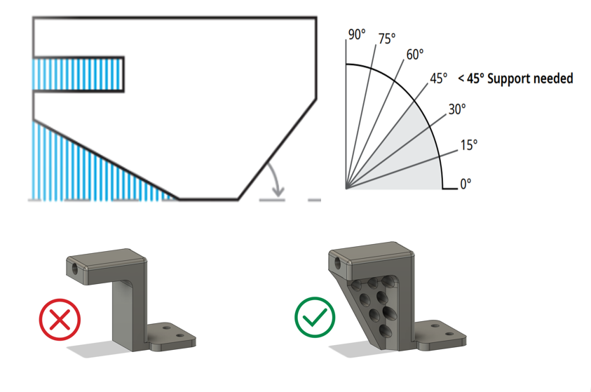
OVERHANG ANGLES
A final criterion concerns the design of parts with overhangs, in particular those geometries that have angles formed with the print bed. As can be seen from the figure, with an angle of less than 45° it is necessary to use supports, otherwise the component could yield during printing as the layers in that area do not find a point of support.
The rules just illustrated allow a successful printing of the part and possibly allow you to make changes and review the component in the design phase according to the desired needs. If you want to develop a new project or revise an existing one, it is advisable to intervene in the design phase and therefore prior to printing.
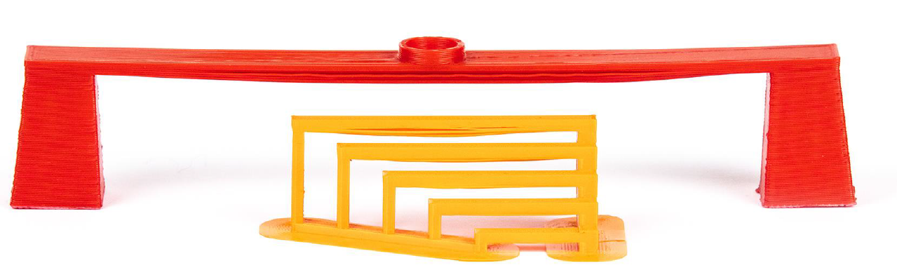
BRIDGING
Bridging in FFF occurs when the printer needs to print between two supports or anchor points. Since there is nothing to build on, no support is offered for the initial layer to be printed and the material tends to sag. Bridges most often occur in horizontal axis holes found in the walls of objects or in the top layer (or roof) of hollow parts. One solution is to reduce the bridge gap, but the impact of this depends on the design constraints of the part. Another solution to avoid sagging is to include support. The support offers a temporary platform on which to build the "bridge" layer. The support material is removed after printing is complete, although it may leave marks or damage the surface where the support was attached to the final part.
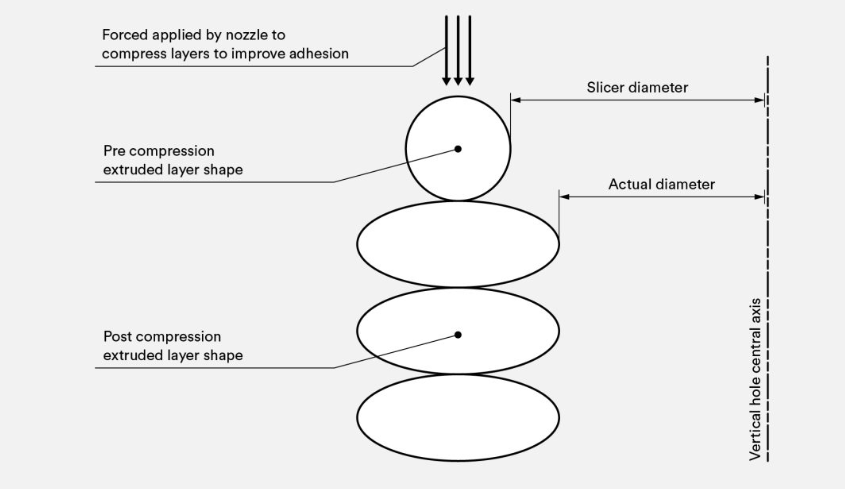
VERTICAL HOLES
FFF printing technology often produces undersized holes in the vertical axis. The printing process for such a hole and why its diameter is reduced can be summarized as follows:
as the nozzle prints the perimeter of a vertical axis hole, it compresses the newly printed layer onto existing build layers to improve adhesion. The compressive force of the nozzle deforms the shape of the round layer extruded from a circle into a larger, flatter shape (see image below). This increases the contact area with the previously printed layer, improving adhesion but enlarging the extruded segment. This causes a decrease in the diameter of the hole to be printed, which can be a problem when printing small diameter holes, whereby the effect is greater due to the ratio of the hole diameter to the nozzle diameter.
In conclusion, the design phase is very important because it allows you to intervene by creating a new project or revising an existing one according to how it must be implemented. Therefore, knowing these rules, it is possible to act before printing by designing with criteria different from those applicable to conventional technologies, with the possibility of having different solutions in the design phase.