")
")
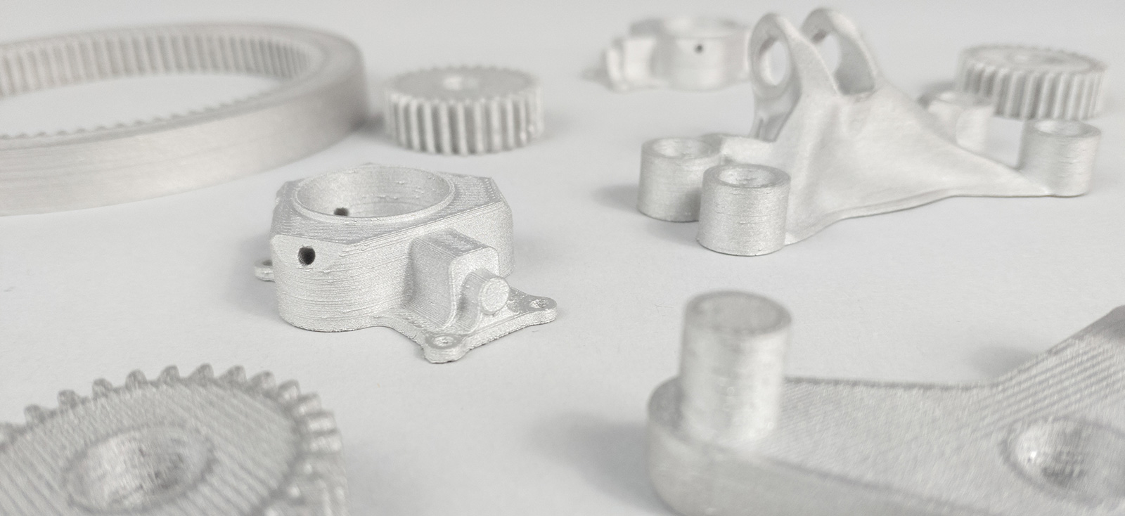
Debinding and Sintering of 3D printed parts with BASF Ultrafuse 316L and 17-4 PH
The 3D Printing of Metal Filaments is part of the already proven Metal Injection Molding (MIM) process.
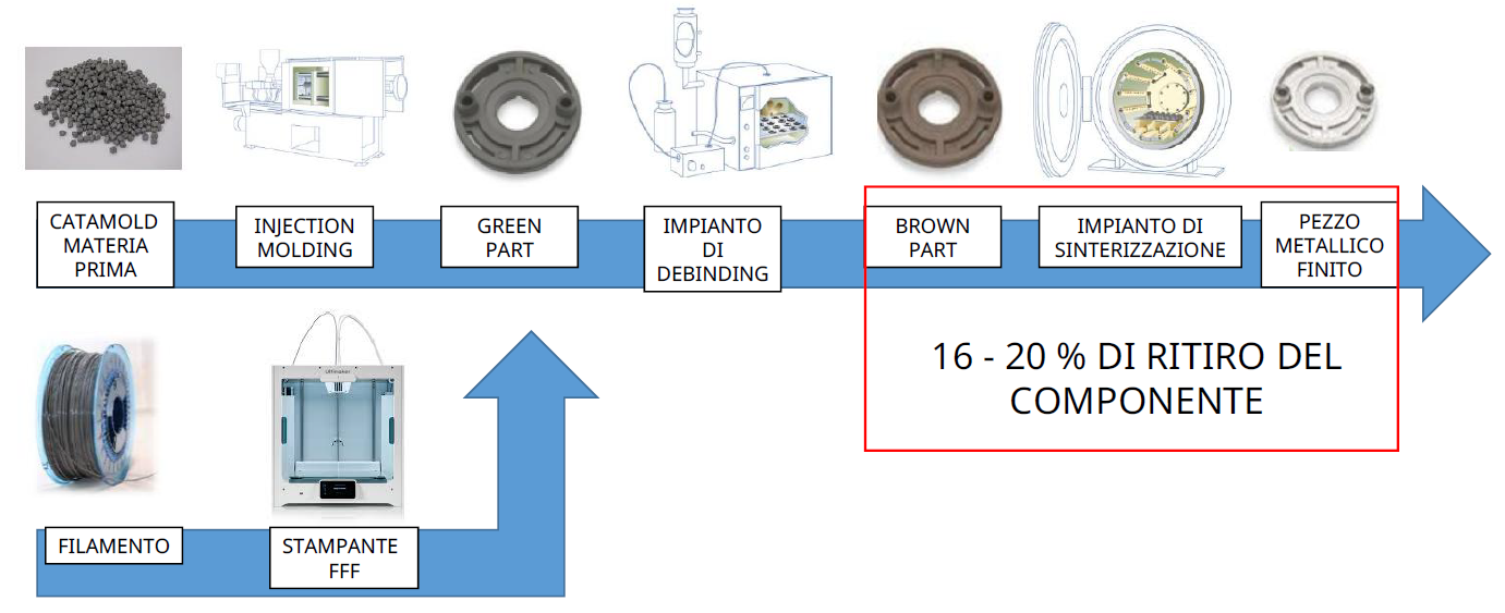
The MIM uses selected metal powders mixed with binding polymers to form a single mixture called feedstock (catamold).
The catamold is injected into a mold in order to obtain the desired shape which is called "green part".
However, the Green Part can be obtained not only with expensive machinery such as the Injection Molding mold but also using a metal filament such as BASF Ultrafuse 316L, the most common austenitic stainless steel, or BASF Ultrafuse 17-4PH, stainless steel with high resistance to corrosion, by extruding the filament with an FFF 3D printer.
The Ultrafuse 316L was profiled by BASF on the Ultimaker S5 3D printer, equipped with a special Print Core ideal for printing abrasive materials such as metal filaments, but can be printed on any printer equipped with an extruder reaching 240°C and print bed 90°C.
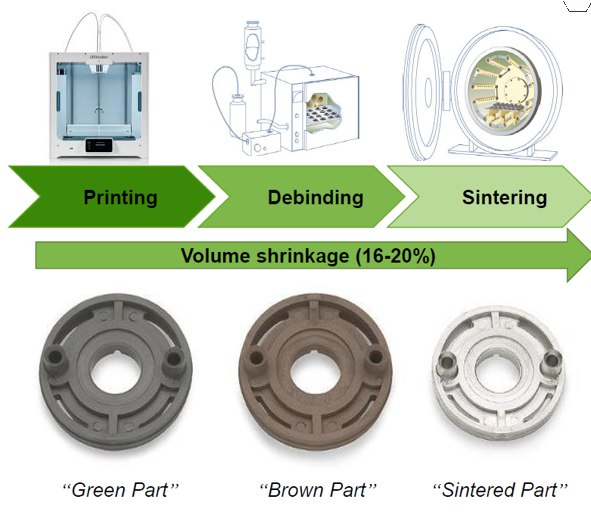
Thermal-chemical treatment of debinding and sintering
After the debinding, treatment of separation of the polymers from the metal, the sintering takes place in a controlled atmosphere at a temperature lower than the melting point.
After sintering, the density obtained will guarantee equivalent mechanical characteristics of investment-cast parts or made in MIM.
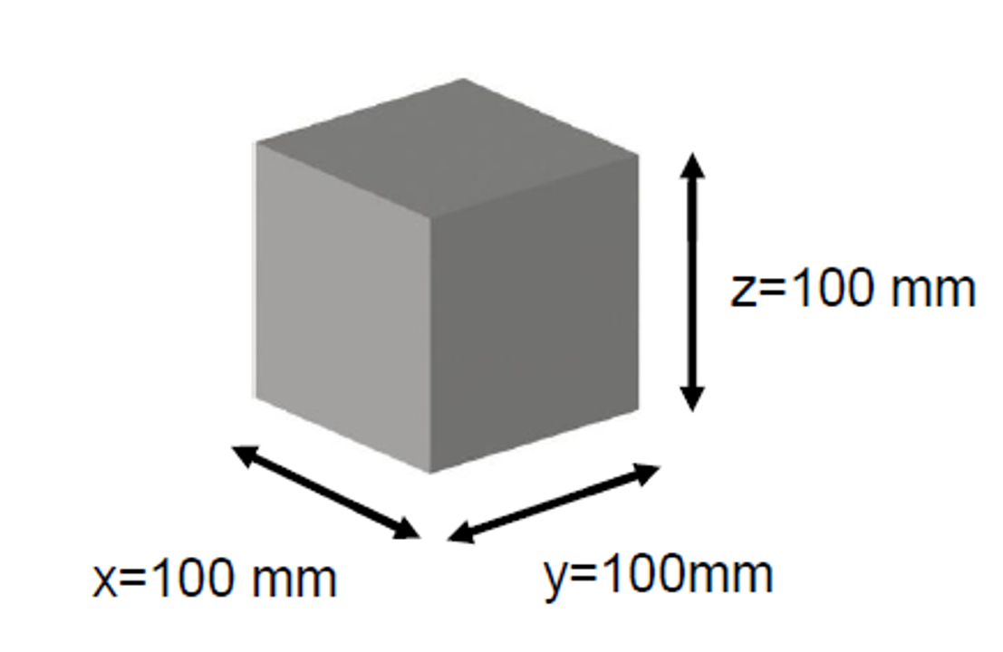
As you can see from the image, the STL model will have to be scaled during the slicing phase to compensate for shrinkage.
Therefore we can set on the slicing software +119,98% on X and Y (316L) or +120% (17-4 PH) and +126,01% on Z.
THREE SERVICES OFFERED BY FASTPARTS:
- 3D printing with Ultrafuse 316L/17-4PH + Debinding and Sintering treatments, by sending the STL/STEP file of the component to be 3D printed
- Treatments of Debinding and Sintering, by sending the component already 3D printed.
- Design guide optimized for Debinding and Sintering treatments.
Guide to the design of components to be 3D printed with 316L
Part size affects component stability during D&S processes.
The limiting factor is the load due to gravity.
Up to 100 mm for each side the result is guaranteed!
To avoid structural collapse, the height must not exceed more than 3 times the thickness of the base and the minimum wall thickness must not be less than 8 tenths of a millimeter (c = 0.8mm).
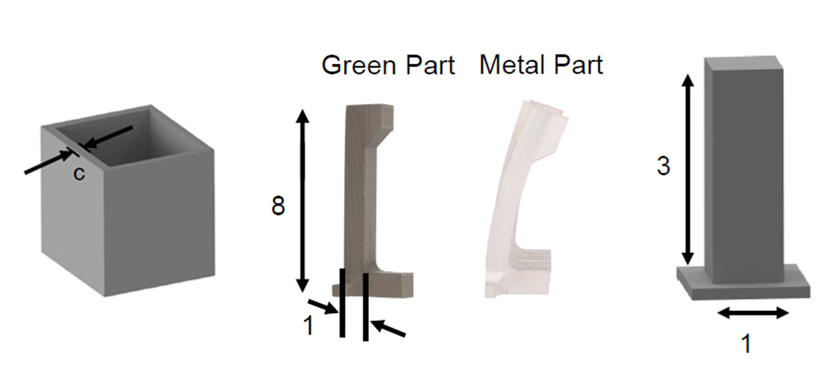
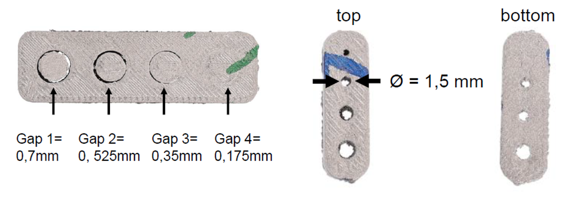
To prevent the holes from closing during sintering it is important to ensure that the gap between 2 parts is always greater than 0.7 mm.
For vertically printed holes, over 8 mm in diameter, it will be necessary to add supports.
NOTES: in case of sending pre-printed pieces to FastParts, these must also include the printed supports with the same metal material used for printing. Supports must not be removed!
Printing parameters
- Extrusion Temperature 240-250°C
- Plate temperature 90-120°C
- Closed Chamber (if available) and Cooling Off
- Recommended Layer Height < 0,15mm to have small gaps between Layers
Why choose this technology
- Low Investment Costs
- Material printable on any FFF printer
- Simple Material Management
- Using Filament, not Powders
- Reliable Post-Processing Services
- Debinding and Sintering