")
")
Functional prototyping of a device for the cooling of a motorcycle braking system
In motorsport, conveyors integrated into the bodywork or as appendages have always been used to cool down components particularly stressed. The goal is to keep the temperatures of these components within the optimal working range, ensuring performance, efficiency and durability of the system.
Angelo Di Gioia at the helm of the design and Giovanni Di Franco at the fluid simulation together engineered a useful motorcycle braking system air cooling duct for a KTM Duke 890 R.
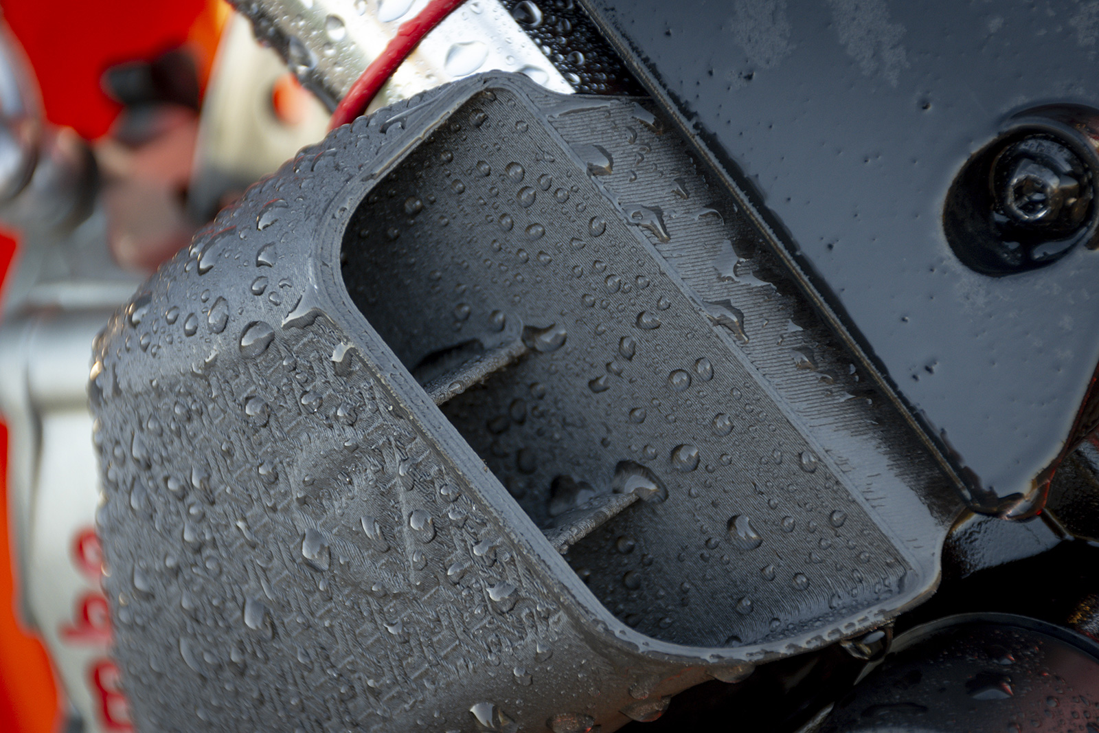
The result is a 100% functional part designed and produced with extreme efficiency in terms of time and costs, thanks to Raise3D solutions for additive manufacturing.
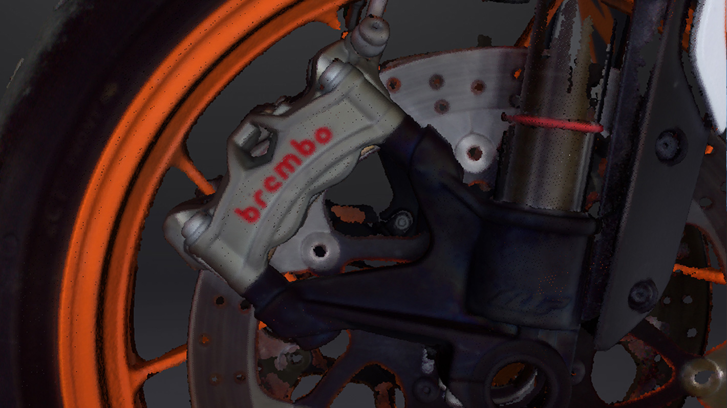
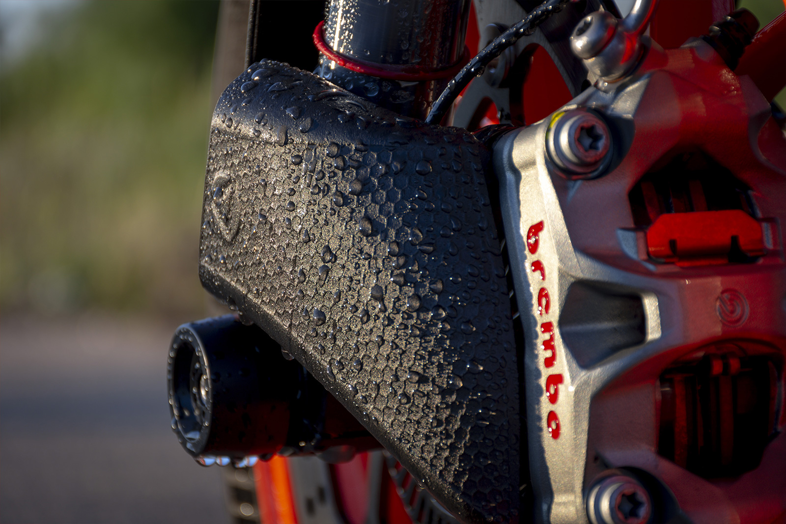
The braking system of any vehicle has the task of dissipating the kinetic energy of the vehicle itself to slow it down or stop it. The temperatures achievable by the system are influenced by the number of braking actions, speed, braking load and materials used. This thermal energy, if prolonged over time, spreads throughout the system, also affecting the fluid that controls the braking operation. In modern braking systems it is easy to find aluminum alloys due to their high coefficient of thermal diffusion. The purpose of this work was to improve the heat exchange of the brake caliper with a consequent reduction in the temperature of the brake fluid through the aid of an air duct.
Reverse Engineering
In the field of Reverse Engineering, thanks to their versatility of use, the market is dominated by laser, structured light or hybrid acquisition devices. The professional Shining3D EinScan HX 3D scanner was used for the present study, due to its extreme ease of use and scan speed.
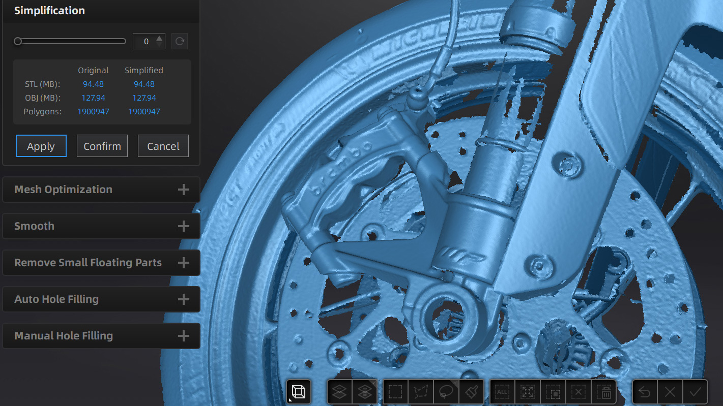
The Rapid-Scan mode combined with texture acquisition by means of a camera integrated in the scanner, allowed a quick scan of the front end of the motorcycle. Through the editing tools included in the EXScan software it is possible to export a scan suitable for your needs and perform operations in succession in a few clicks, such as:
- Mesh simplification
- Mesh optimization
- Removing small surfaces
These operations, which can be performed within the software, greatly simplify the designers' workflow, allowing them to focus on more complex problems.
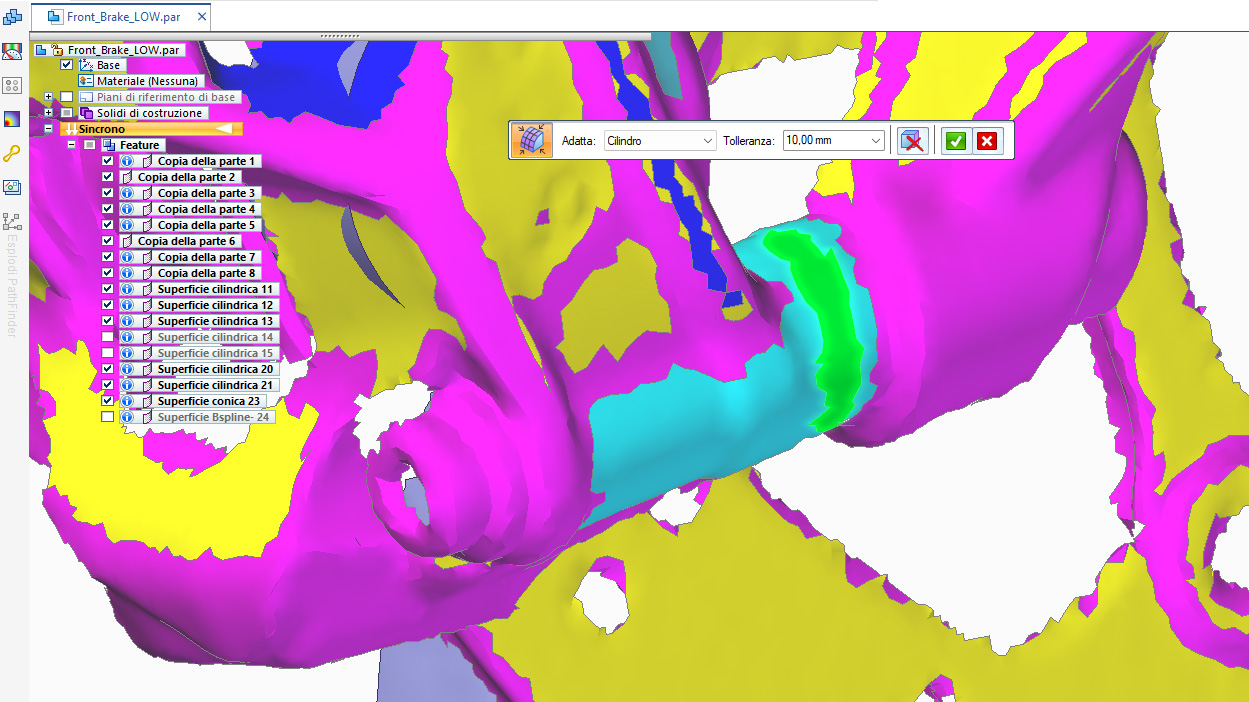
Through the direct export tool to the most popular software suitable for reverse engineering, including Solid Edge by Siemens, the primitive reference geometries have been extracted. These will be the basis for the modeling of the new part.
DESIGN for ADDITIVE MANUFACTURING
A component designed for the technology!
Although it may seem a risky and premature choice to bind to a certain technology, actually it is not always so.
Many times, FFF technology has proven to be more advantageous in small series parts production parts, on demand components, and great for customization. All this thanks to its extreme versatility, ease of use and low cost of ownership; therefore, why not fully exploit its potential?
- MINIMUM WALL THICKNESS: 0.8 mm (4*LW)
- MAXIMUM OVERHANG: 40°
- RECESSED DETAILS: 0.5 mm
- HORIZONTAL BRIDGES: < 10 mm
These are just some of the rules to be respected for a good design for additive manufacturing.
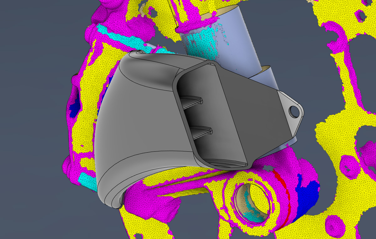
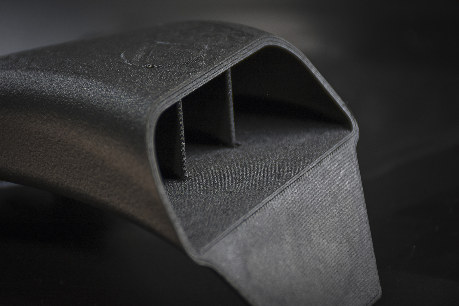
Producing efficiently also means optimizing material waste through a geometry that doesn’t require supports but at the same time remains consistent in the construction direction. The achievement of this goal was possible by splitting the component into 2 parts which can be coupled together by a snap-fit connection.
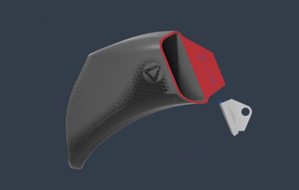
The main advantages of the following assembly method are the speed and assembly simplicity as it doesn’t require specific tools or fasteners.
The effectiveness of the joint depends on the dimensional tolerances obtained, which also depend on the Rapid Prototyping technique used.
The study on 2 models' orientation, moreover, allowed us to prevent the interlocking from being influenced by the staircase effect.
FLUID DYNAMICS SIMULATION
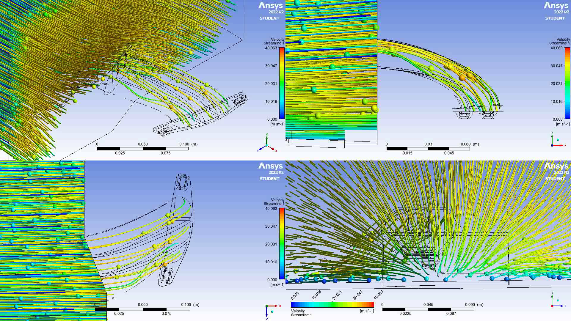
To validate the effectiveness of the component, at least in terms of acceleration and flow homogeneity, fluid dynamic analyses were conducted using ANSYS 2022 Fluent working environment.
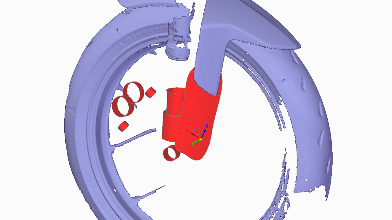
The geometry of the air duct has been repeated several times to obtain acceptable results. Part of the front fender was also reverse engineered to verify its influence on the flow behavior inside the air duct.
The simulations allowed the improvement of the design to optimize the results.
Subsequent tests carried out on a test bench / wind tunnel (using sensors installed on the vehicle) and then on test circuits, will be used to measure the actual heat exchange with surfaces subject to sudden temperature increases (brake discs, pads and calipers).
PRODUCTION WITHOUT LIMITS
Another valid reason that supports the choice of FFF technology to produce end-use parts is the wide choice of engineering thermoplastic materials available today. By virtue of the final requirements of the application, the choice fell on CFRPs (Carbon Fiber Reinforced Plastics) and specifically on Braskem's FF900PP-CF, a polypropylene reinforced with 100% recycled carbon fibers.
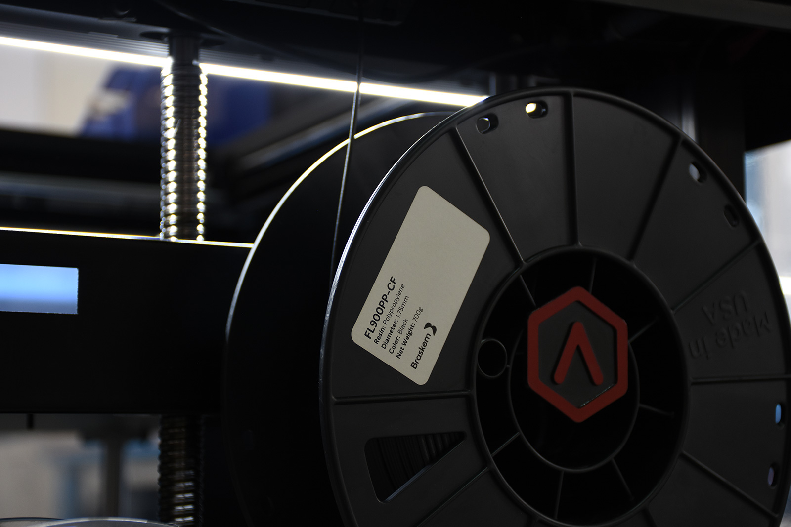
Polypropylene is a widely used material in the automotive sector and stands out from the others for its excellent properties.
Specifically, this thermoplastic enriched with carbon fibers maximizes the characteristics of this product making it ultralight and resistant to the impacts of debris.
In addition, its excellent resistance to water and chemicals makes it a particularly suitable material for outdoor use that is resistant to rain and smog products.
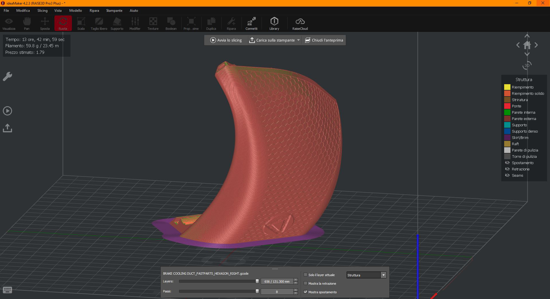
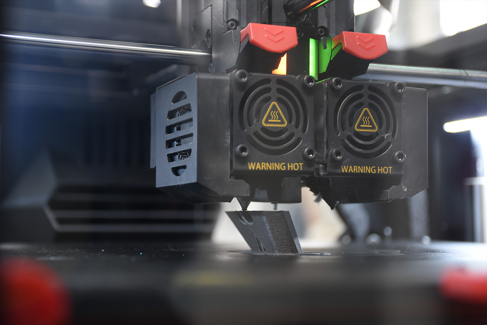
High print resolution, reliability and precision are the winning ingredients for a high-performance product with an attractive design, and the Raise3D Pro3 3D printer is the ideal tool for small batch production of end-use parts.
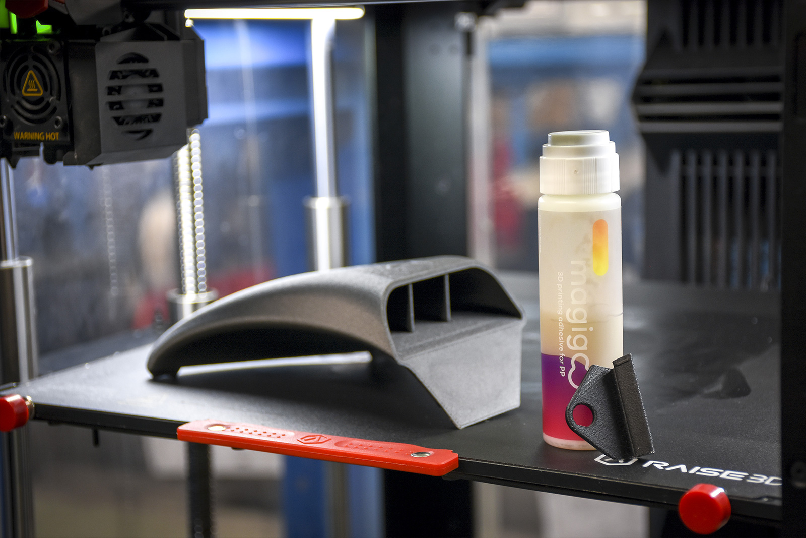
Thanks to the wide collection of material profiles available on the online library ideamaker.io, generating the .gcode is really simple, as well as the management of the print queues thanks to the ability to monitor and control the printer via wireless connectivity.
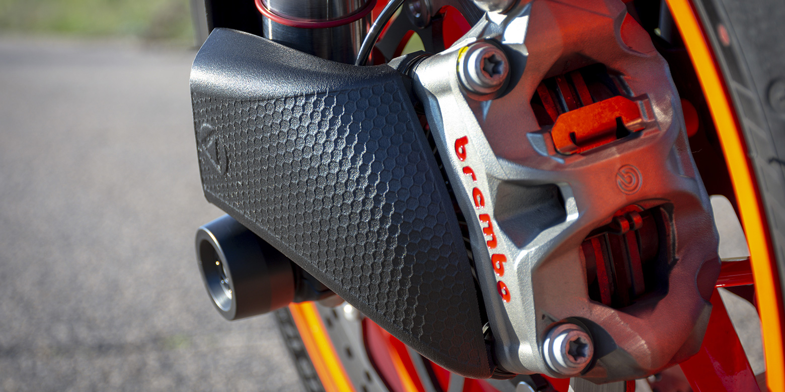
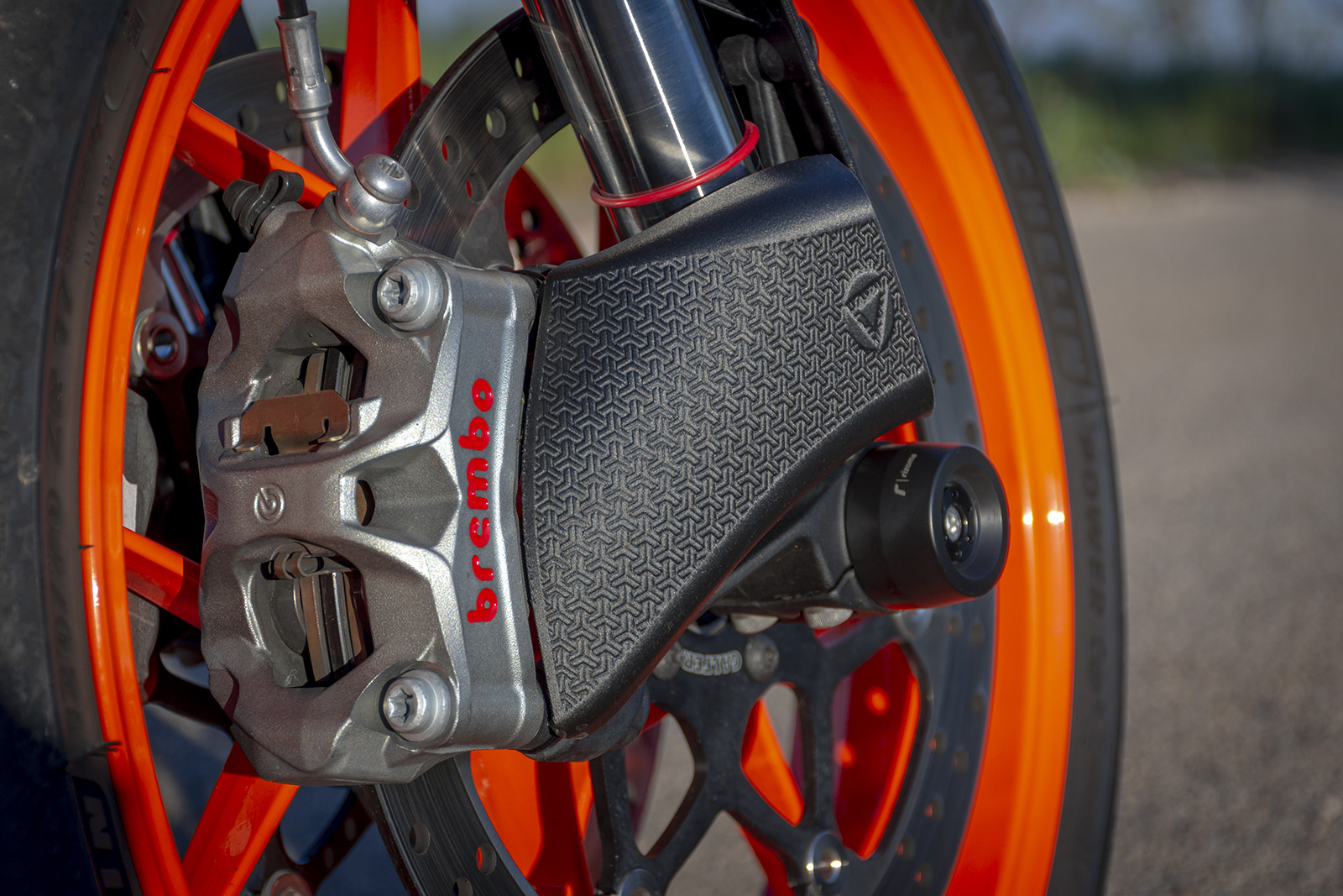
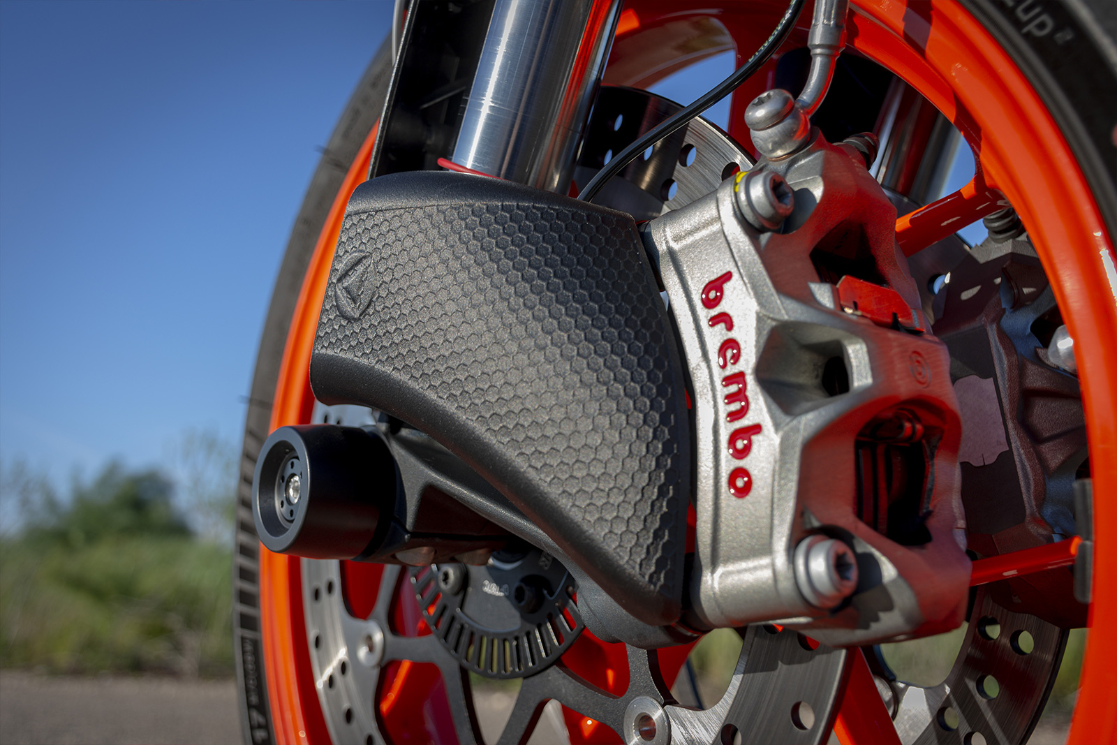
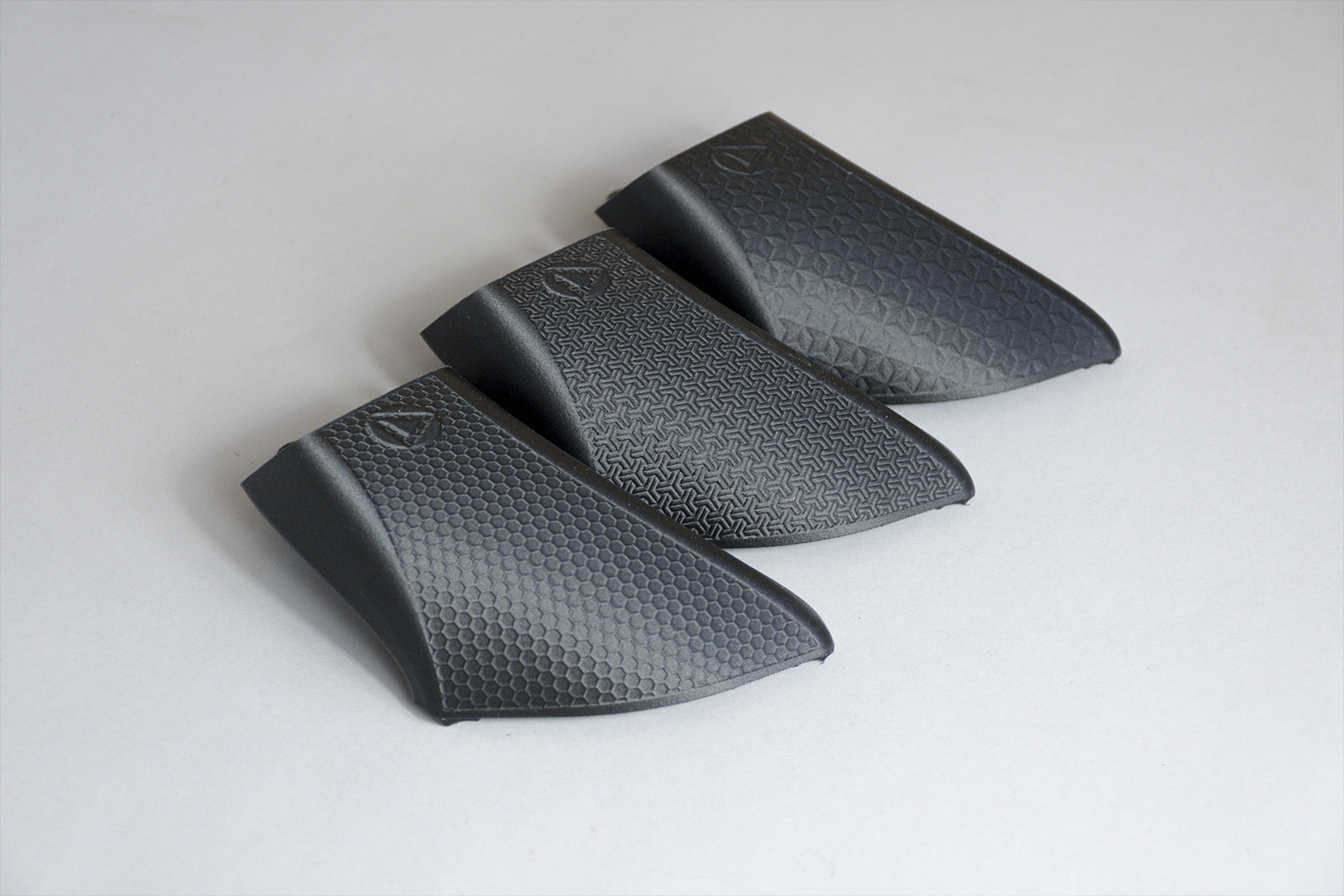
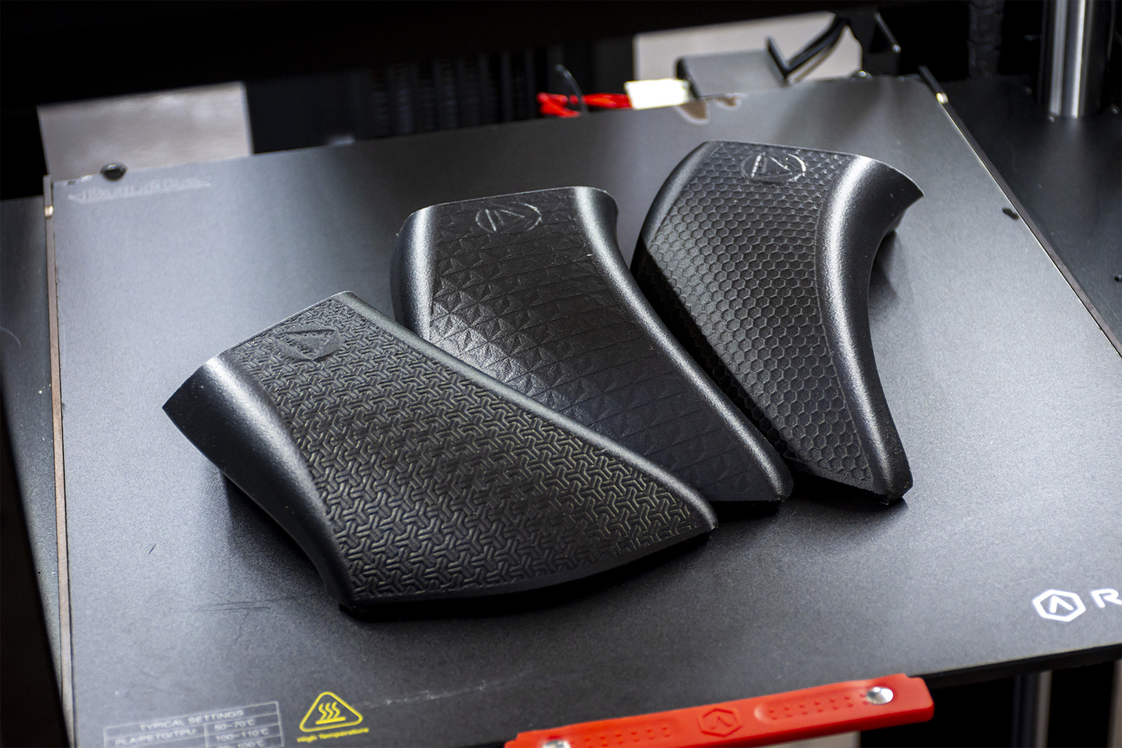
CUSTOMIZED PROCTION
Nothing is more tempting than a product that can be customized. To express this concept, we decided to decorate this component with different three-dimensional textures - perhaps to match your logo.
CONCLUSIONS
The workflow used in this study demonstrates the incredible potential of modern reverse engineering techniques which, combined with additive manufacturing technologies, can lead to the improvement of product performance and the creation of new ones.
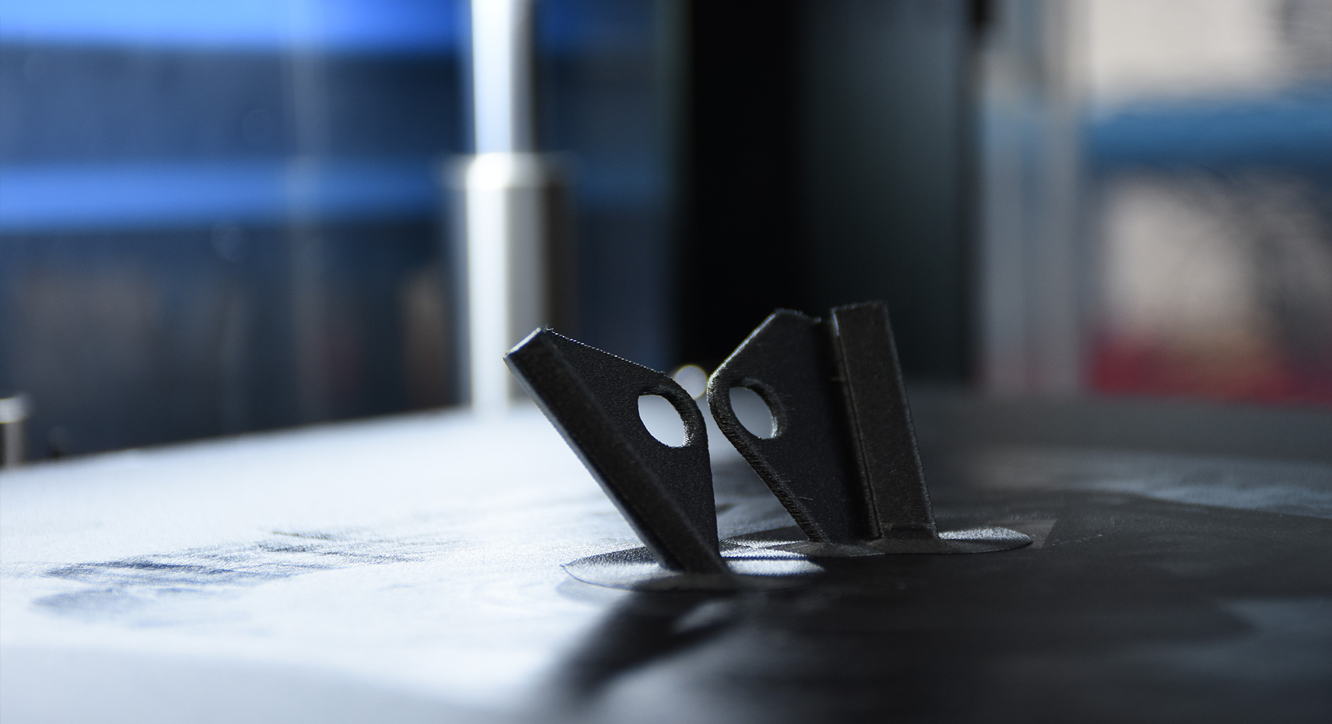
Excluding the design and modeling time of the component, in a total of 16 hours it was possible to obtain the first conceptual prototype (scanning, post-processing and prototyping) with fully satisfactory results. Furthermore, the cost applied by FastParts for the production of the pair of conveyors is around €100, against a market value of these special components which can reach up to €300.
The assembly check on the vehicle confirmed the validity of the method from all points of view.
All that remains is the road test!